Sunday, August 31, 2008

What is GPS?


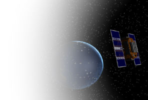
The Global Positioning System (GPS) is a satellite-based navigation system made up of a network of 24 satellites placed into orbit by the U.S. Department of Defense. GPS was originally intended for military applications, but in the 1980s, the government made the system available for civilian use. GPS works in any weather conditions, anywhere in the world, 24 hours a day. There are no subscription fees or setup charges to use GPS.

Antenna (radio)


An antenna is a transducer designed to transmit or receive electromagnetic waves. In other words, antennas convert electromagnetic waves into electrical currents and vice versa. Antennas are used in systems such as radio and television broadcasting, point-to-point radio communication, wireless LAN, radar, and space exploration. Antennas usually work in air or outer space, but can also be operated under water or even through soil and rock at certain frequencies for short distances.
Physically, an antenna is an arrangement of conductors that generate a radiating electromagnetic field in response to an applied alternating voltage and the associated alternating electric current, or can be placed in an electromagnetic field so that the field will induce an alternating current in the antenna and a voltage between its terminals. Some antenna devices (parabolic antenna, Horn Antenna) just adapt the free space to another type of antenna.
Thomas Edison used antennas by 1885. Edison patented his system in U.S. Patent 465,971 . Antennas were also used in 1888 by Heinrich Hertz (1857-1894) to prove the existence of electromagnetic waves predicted by the theory of James Clerk Maxwell. Hertz placed the emitter dipole in the focal point of a parabolic reflector. He published his work and installation drawings in Annalen der Physik und Chemie (vol. 36, 1889).

notes about the function generator


The High Speed Function Generator was published in the professional electronics section of the Aug 1996 issue of Electronics Australia, and has proven to be extremely popular. The kit is no longer available from any of the kit suppliers.
The project is capable of generating 20MHz or greater Sine, Square, Triangle, and TTL There is a problem with the TTL output when the generator is used on the LOW and MEDIUM frequency ranges AND the MAIN frequency adjust control is set to the lower 15% of it's range. Any significant loading on the TTL output will cause it to osscillate on the positive and negative edges. This is apparently an inherent problem with the MAX038 chip !. The only solution is to buffer the SYNC output of the MAX038 with a 74HC14 schmitt inverter. This can be mounted on a small piece of vero-board along with R10 and a bypass capacitor. Use the other 5 inverters in the package in parallel to provide a high current buffered output. Be sure to connect the supply pins of the 74HC14 directly to pins 15 and 16 of the MAX038. waveforms.

ic 555 timer


The 555 is an integrated circuit (chip) implementing a variety of timer and multivibrator applications. The IC was designed and invented by Hans R. Camenzind. It was designed in 1970 and introduced in 1971 by Signetics (later acquired by Philips). The original name was the SE555/NE555 and was called "The IC Time Machine". The 555 gets its name from the three 5-kOhm resistors used in typical early implementations (Reference 1). It is still in wide use, thanks to its ease of use, low price and good stability. As of 2003, 1 billion units are manufactured every year.
The 555 timer is one of the most popular and versatile integrated circuits ever produced. It includes 23 transistors, 2 diodes and 16 resistors on a silicon chip installed in an 8-pin mini dual-in-line package (DIP-8). The 556 is a 14-pin DIP that combines two 555s on a single chip. The 558 is a 16-pin DIP that combines four slightly modified 555s on a single chip (DIS & THR are connected internally, TR is falling edge sensitive instead of level sensitive). Also available are ultra-low power versions of the 555 such as the 7555 and TLC555. The 7555 requires slightly different wiring using fewer external components and less power.

Saturday, August 30, 2008

13.8V 20A linear power supply


Linear power supplies for communication equipment are among the most commonly built electronic projects. Almost every technically inclined radio amateur has built at least one. But unfortunately most designs, even those published in well respected books, are unnecessarily complicated, or have some specific drawbacks. The design presented here is a little bit unusual in its arrangement, but offers some advantages over the usual designs that I will explain in the following paragraphs.

DC Motor Control Circuit


Here, S1 and S2 are normally open , push to close, press button switches. The diodes can be red or green and are there only to indicate direction. You may need to alter the TIP31 transistors depending on the motor being used. Remember, running under load draws more current. This circuit was built to operate a small motor used for opening and closing a pair of curtains. As an advantage over automatic closing and opening systems, you have control of how much, or how little light to let into a room. The four diodes surriunding the motor, are back EMF diodes. They are chosen to suit the motor. For a 12V motor drawing 1amp under load, I use 1N4001 diodes.